- 您现在的位置:买卖IC网 > Sheet目录505 > RXM-869-ES_ (Linx Technologies Inc)RECEIVER RF 869MHZ 16PIN SMD
PIN ASSIGNMENTS
1
2
3
4
5
6
7
8
ANT
GND
NC
GND
VCC
NC
NC
NC
NC
NC
PDN
RSSI
DATA
AUDIO
A REF
NC
16
15
14
13
12
11
10
9
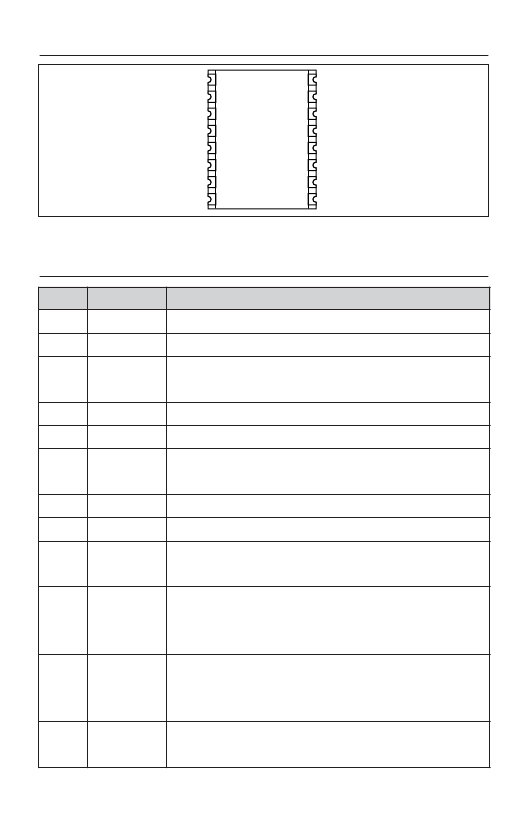
Figure 7: ES Series Receiver Pinout (Top View)
PIN DESCRIPTIONS
Pin #
1
2
3
4
5
6-9
10
11
12
13
14
15 - 16
Page 4
Name
ANT
GND
NC
GND
V CC
NC
A REF
AUDIO
DATA
RSSI
PDN
NC
Description
50-ohm RF Input
Analog Ground
No Electrical Connection. Soldered for physical support
only.
Analog Ground
Supply Voltage
No Electrical Connection. Soldered for physical support
only.
Audio RMS (Average) Voltage Reference
Recovered Analog Output
Digital Data Output. This line will output the demodulated
digital data.
Received Signal Strength Indicator. This line will supply an
analog voltage that is proportional to the strength of the
received signal.
Power Down. Pulling this line low will place the receiver
into a low-current state. The module will not be able to
receive a signal in this state.
No Electrical Connection. Soldered for physical support
only.
发布紧急采购,3分钟左右您将得到回复。
相关PDF资料
RXM-GPS-SG-T
GPS MODULE SMD SIRF
RXM-GPS-SR-T
GPS MODULE SMD SIRF W/ANT
RZE002P02TL
MOSFET P-CH 20V 200MA EMT3
RZF020P01TL
MOSFET P-CH 12V 2A TUMT3
RZF030P01TL
MOSFET P-CH 12V 3A TUMT3
RZM002P02T2L
MOSFET P-CH 20V 0.2A UMT6
RZQ045P01TR
MOSFET P-CH 12V 4.5A TSMT6
RZQ050P01TR
MOSFET P-CH 12V 5A TSMT6
相关代理商/技术参数
RXM-900-HP3
制造商:未知厂家 制造商全称:未知厂家 功能描述:HP3 SERIES RECEIVER MODULE DATA
RXM-900-HP3-PPO
功能描述:射频模块 RF Receiver 900MHz 8-CH SIP Pack
RoHS:否 制造商:Linx Technologies 产品:Transceiver Modules 频带:902 MHz to 928 MHz 输出功率:- 15.5 dBm to + 12.5 dBm 接口类型:UART 工作电源电压:- 0.3 VDC to + 5.5 VDC 传输供电电流:38.1 mA 接收供电电流:22.7 mA 天线连接器类型:U.FL 最大工作温度:+ 85 C 尺寸:1.15 mm x 0.63 mm x 0.131 mm
RXM-900-HP3-PPO_
功能描述:RECEIVER RF 900MHZ 8-CHANNEL RoHS:是 类别:RF/IF 和 RFID >> RF 接收器 系列:HP3 产品培训模块:Lead (SnPb) Finish for COTS 产品变化通告:Product Discontinuation 09/Jan/2012 标准包装:50 系列:* 频率:850MHz ~ 2.175GHz 灵敏度:- 数据传输率 - 最大:- 调制或协议:- 应用:* 电流 - 接收:* 数据接口:PCB,表面贴装 存储容量:- 天线连接器:PCB,表面贴装 特点:- 电源电压:4.75 V ~ 5.25 V 工作温度:0°C ~ 85°C 封装/外壳:40-WFQFN 裸露焊盘 供应商设备封装:40-TQFN-EP(6x6) 包装:托盘
RXM-900-HP3-PPS
功能描述:射频模块 RF Receiver 900MHz 8 & 100-CH SIP Pack RoHS:否 制造商:Linx Technologies 产品:Transceiver Modules 频带:902 MHz to 928 MHz 输出功率:- 15.5 dBm to + 12.5 dBm 接口类型:UART 工作电源电压:- 0.3 VDC to + 5.5 VDC 传输供电电流:38.1 mA 接收供电电流:22.7 mA 天线连接器类型:U.FL 最大工作温度:+ 85 C 尺寸:1.15 mm x 0.63 mm x 0.131 mm
RXM-900-HP3-PPS_
功能描述:RECEIVER RF 900MHZ 8PAR/120SRLCH RoHS:是 类别:RF/IF 和 RFID >> RF 接收器 系列:HP3 产品培训模块:Lead (SnPb) Finish for COTS 产品变化通告:Product Discontinuation 09/Jan/2012 标准包装:50 系列:* 频率:850MHz ~ 2.175GHz 灵敏度:- 数据传输率 - 最大:- 调制或协议:- 应用:* 电流 - 接收:* 数据接口:PCB,表面贴装 存储容量:- 天线连接器:PCB,表面贴装 特点:- 电源电压:4.75 V ~ 5.25 V 工作温度:0°C ~ 85°C 封装/外壳:40-WFQFN 裸露焊盘 供应商设备封装:40-TQFN-EP(6x6) 包装:托盘
RXM-900-HP3-SPO
功能描述:射频模块 RF Receiver 900MHz 8-CH SMD Pack
RoHS:否 制造商:Linx Technologies 产品:Transceiver Modules 频带:902 MHz to 928 MHz 输出功率:- 15.5 dBm to + 12.5 dBm 接口类型:UART 工作电源电压:- 0.3 VDC to + 5.5 VDC 传输供电电流:38.1 mA 接收供电电流:22.7 mA 天线连接器类型:U.FL 最大工作温度:+ 85 C 尺寸:1.15 mm x 0.63 mm x 0.131 mm
RXM-900-HP3-SPO_
功能描述:RECEIVER RF 900MHZ 8-CH SMD RoHS:是 类别:RF/IF 和 RFID >> RF 接收器 系列:- 产品培训模块:Lead (SnPb) Finish for COTS 产品变化通告:Product Discontinuation 09/Jan/2012 标准包装:50 系列:* 频率:850MHz ~ 2.175GHz 灵敏度:- 数据传输率 - 最大:- 调制或协议:- 应用:* 电流 - 接收:* 数据接口:PCB,表面贴装 存储容量:- 天线连接器:PCB,表面贴装 特点:- 电源电压:4.75 V ~ 5.25 V 工作温度:0°C ~ 85°C 封装/外壳:40-WFQFN 裸露焊盘 供应商设备封装:40-TQFN-EP(6x6) 包装:托盘
RXM-900-HP3-SPS
功能描述:射频模块 RF Receiver 900MHz 8 & 100-CH SMD Pack
RoHS:否 制造商:Linx Technologies 产品:Transceiver Modules 频带:902 MHz to 928 MHz 输出功率:- 15.5 dBm to + 12.5 dBm 接口类型:UART 工作电源电压:- 0.3 VDC to + 5.5 VDC 传输供电电流:38.1 mA 接收供电电流:22.7 mA 天线连接器类型:U.FL 最大工作温度:+ 85 C 尺寸:1.15 mm x 0.63 mm x 0.131 mm
